Symbol

사용 코드_1
|
1
2
3
4
5
6
7
8
|
module or_gate (in, out);
input [2:0] in; // 3비트 입력 버스 (in[2], in[1], in[0])
output out; // 1비트 출력
// 리덕션 OR 연산: 3비트 입력의 모든 비트를 OR 연산
assign out = |in[2:0];
endmodule
|
cs |
사용 코드_2
|
1
2
3
4
5
6
7
8
9
10
11
|
module or_gate (in2, in1, in0, out);
input in2; // 첫 번째 입력 (개별 1비트)
input in1; // 두 번째 입력 (개별 1비트)
input in0; // 세 번째 입력 (개별 1비트)
output out; // 1비트 출력
// 개별 입력들을 직접 OR 연산
// 세 개의 입력 중 하나라도 1이면 출력이 1
assign out = in2 | in1 | in0;
endmodule
|
cs |
사용 코드_3
|
1
2
3
4
5
6
7
8
9
10
11
|
module or_gate (
input [2:0] in, // 3비트 입력 버스 (in[2], in[1], in[0])
output out // 1비트 출력
);
// reduction OR 연산을 사용하여
// in[2], in[1], in[0] 중 하나라도 1이면 out은 1
assign out = ~(in[2:0] == 3'b000);
endmodule
|
cs |
사용 코드_4
|
1
2
3
4
5
6
7
8
9
10
11
|
module or_gate (
input [2:0] in, // 3비트 입력 버스 (in[2], in[1], in[0])
output out // 1비트 출력
);
// reduction OR 연산을 사용하여
// in[2], in[1], in[0] 중 하나라도 1이면 out은 1
assign out = (in[2:0] != 3'b000);
endmodule
|
cs |
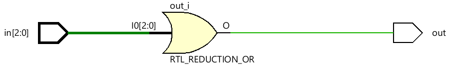
Schematic
'Verilog_RTL 설계' 카테고리의 다른 글
| [Verilog_RTL]_MUX (0) | 2025.06.14 |
|---|---|
| [Verilog_RTL]_FULL_ADDER_GATE (0) | 2025.06.14 |
| [Verilog_RTL]_HALF_ADDER_GATE (0) | 2025.06.13 |
| [Verilog_RTL]_NOR_GATE (0) | 2025.06.13 |
| [Verilog_RTL]_INVERTER (0) | 2025.06.13 |