사용 코드
|
1
2
3
4
5
6
7
8
9
10
11
|
module inverter (in, out);
input in; // 입력 신호 (1비트)
output out; // 출력 신호 (1비트)
wire out; // out 신호는 wire 타입 (output은 기본적으로 wire이므로 이 줄은 생략 가능)
// assign 문을 사용하여 in의 반전 값을 out에 할당
// 입력이 1이면 출력은 0, 입력이 0이면 출력은 1
assign out = ~in;
endmodule
|
cs |
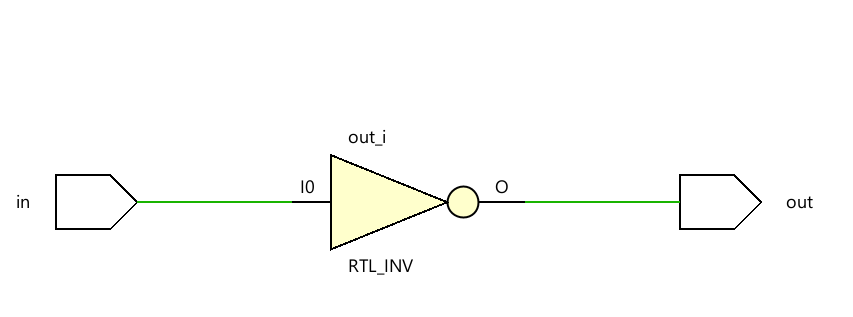
Schematic
'Verilog_RTL 설계' 카테고리의 다른 글
| [Verilog_RTL]_MUX (0) | 2025.06.14 |
|---|---|
| [Verilog_RTL]_FULL_ADDER_GATE (0) | 2025.06.14 |
| [Verilog_RTL]_HALF_ADDER_GATE (0) | 2025.06.13 |
| [Verilog_RTL]_NOR_GATE (0) | 2025.06.13 |
| [Verilog_RTL]_OR_GATE (0) | 2025.06.13 |