Symbol

사용 코드
|
1
2
3
4
5
6
7
8
9
10
11
12
13
|
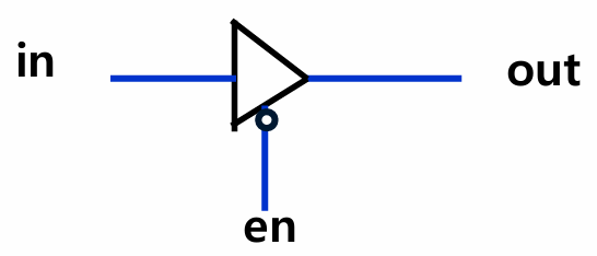
module tri_state_inverter (in, en, out);
input in; // 입력 신호 (in)
input en; // 출력 enable 신호 (en = 1일 때 in을 out으로 전달, en = 0일 때 high impedance)
output out; // 출력 신호
wire out;
// en = 1이면 out = in
// en = 0이면 out = high impedance (1'bz)
assign out = en ? in : 1'bz;
enmodule
|
cs |
Schematic
Symbol
사용 코드
|
1
2
3
4
5
6
7
8
9
10
11
12
|
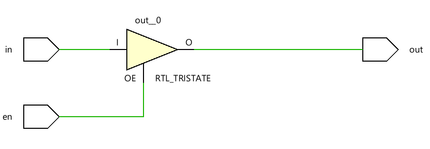
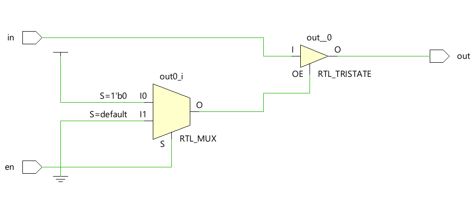
module tri_state_buffer (in, en, out);
input in; // 입력 신호 (in)
input en; // 출력 제어 신호 (en)
output out; // 출력 신호
wire out; // ❗ output은 기본적으로 wire 타입이므로 중복 선언 (Vivado 등에서는 경고나 오류 가능)
// en = 0이면 out = in (버퍼 동작)
// en = 1이면 out = high impedance (출력 끔)
assign out = !en ? in : 1'bz;
endmodule
|
cs |
Schematic
'Verilog_RTL 설계' 카테고리의 다른 글
| [Verilog]_4BIT_ADDER/SUBTRACTOR (0) | 2025.06.14 |
|---|---|
| [Verilog]_4BIT_ADDER (0) | 2025.06.14 |
| [Verilog_RTL]_4BIT_MUX (0) | 2025.06.14 |
| [Verilog_RTL]_MUX (0) | 2025.06.14 |
| [Verilog_RTL]_FULL_ADDER_GATE (0) | 2025.06.14 |